RAD DATA COMMUNICATIONS
FOM-E1/T1 (DC POWER, SMA CONNECTOR)
|
Card Type |
T1/E1 interface converter |
|
Chipset |
Unidentified |
|
Wire Type |
Fiber optic cable |
|
T1/E1 Transfer Rate |
1.544Mbps/2.048Mbps |
|
T1/E1 Protocol |
B8ZS, HDB3 |
|
Frame Type |
Unidentified |
|
Data Bus |
N/A |
|
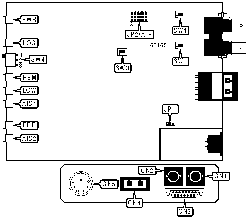
CONNECTIONS | |||
|
Function |
Label |
Function |
Label |
|
Unbalanced T1 signal in via coaxial cable connector |
CN1 |
T1 signal in/out via fiber optic SMA connector |
CN4 |
|
Unbalanced T1 signal out via coaxial cable connector |
CN2 |
DC power in |
CN5 |
|
Balanced T1 signal in/out via DB-15 connector |
CN3 | ||
|
Note:Either connector CN3 or connectors CN1 and CN2 may be used, but not both. | |||
|
USER CONFIGURABLE SETTINGS | |||
|
Setting |
Label |
Position | |
| » |
Signal ground connected to chassis ground |
JP1 |
Pins 1 & 2 closed |
|
Signal ground not connected to chassis ground |
JP1 |
Pins 2 & 3 closed | |
| » |
CN1 shield not connected to chassis ground |
SW1 |
On |
|
CN1 shield connected to chassis ground |
SW1 |
Off | |
| » |
CN2 shield not connected to chassis ground |
SW2 |
On |
|
CN2 shield connected to chassis ground |
SW2 |
Off | |
| » |
Device will transmit All Ones Signal when major alarm is detected |
SW3 |
On |
|
Device will transmit nothing when major alarm is detected |
SW3 |
Off | |
|
ELECTRICAL CABLE TYPE SELECTION | |||||||
|
Setting |
JP2/A |
JP2/B |
JP2/C |
JP2/D |
JP2/E |
JP2/F | |
|
Unbalanced 75 ohm |
Pins 3 & 4 |
Pins 3 & 4 |
Pins 3 & 4 |
Pins 3 & 4 |
Pins 3 & 4 |
Pins 3 & 4 | |
|
Balanced 100 ohm |
Pins 1 & 2 |
Pins 1 & 2 |
Pins 1 & 2 |
Pins 1 & 2 |
Pins 1 & 2 |
Pins 1 & 2 | |
| » |
Balanced 120 ohm |
Pins 2 & 3 |
Pins 2 & 3 |
Pins 2 & 3 |
Pins 2 & 3 |
Pins 2 & 3 |
Pins 2 & 3 |
|
Note:Pins designated are in closed position. | |||||||
|
TEST MODE | ||
|
Setting |
SW4 | |
| » |
Normal operation |
Position 2 |
|
Local loopback test |
Position 1 | |
|
Remote loopback test |
Position 3 | |
|
DIAGNOSTIC LED(S) | |||
|
LED |
Color |
Status |
Condition |
|
PWR |
Green |
On |
Power is on |
|
PWR |
Green |
Off |
Power is off |
|
LOC |
Yellow |
On |
Device is in local loopback test mode |
|
LOC |
Yellow |
Off |
Device is not in local loopback test mode |
|
REM |
Yellow |
On |
Device is in remote loopback test mode |
|
REM |
Yellow |
Off |
Device is not in remote loopback test mode |
|
LOW |
Red |
On |
Electrical input signal is below valid signal level |
|
LOW |
Red |
Off |
Electrical input signal is within valid signal levels |
|
AIS1 |
Yellow |
On |
All Ones Signal received on electrical interface |
|
AIS1 |
Yellow |
Off |
All Ones Signal not received on electrical interface |
|
ERR |
Red |
On |
Bit Error Rate of optical interface is 10 -6 or worse |
|
ERR |
Red |
Off |
Bit Error Rate of optical interface is better than 10 -6 |
|
AIS2 |
Yellow |
On |
All Ones Signal received on fiber optic interface |
|
AIS2 |
Yellow |
Off |
All Ones Signal not received on fiber optic interface |