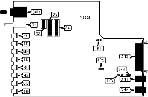
MOTOROLA, INC.
EC 212A/D
|
Card Type |
Modem (asynchronous) |
|
Chip Set |
Unidentified |
|
Maximum Data Rate |
1200bps |
|
Data Bus |
External |
|
Data Modulation Protocol |
Bell 212A |
|
Error Correction |
Unidentified |

|
CONNECTIONS | ||||||
|
Function |
Label |
Function |
Label | |||
|
Line out |
CN1 |
Unidentified |
R1 | |||
|
Line in |
CN2 |
Unidentified |
SW1 | |||
|
RS-232/422 |
CN3 | |||||
|
USER CONFIGURABLE SETTINGS | ||
|
Setting |
Label |
Position |
|
í Chassis ground connected to signal ground |
JP1 |
Pins 2 & 3 closed |
|
Chassis ground not connected to signal ground |
JP1 |
Pins 1 & 2 closed |
|
í Transmit level set to -9 (permissive) |
JP2 |
Pins 2 & 3 closed |
|
Transmit level set to programmable |
JP2 |
Pins 1 & 2 closed |
|
í Auto-dialer enabled |
S2/1 |
On |
|
Auto-dialer disabled |
S2/1 |
Off |
|
í XXXT<CR> escape sequence enabled |
S2/2 |
On |
|
XXXT <CR> escape sequence disabled |
S2/2 |
Off |
|
í Speed set to 1200bps when pin 23 of RS-232 port is high |
S2/3 |
On |
|
Pin 23 of RS-232 port ignored |
S2/3 |
Off |
|
í Analog loopback test performed when pin 25 of RS-232 port is high |
S2/4 |
On |
|
Pin 25 of RS-232 port ignored |
S2/4 |
Off |
|
í Disconnect modem on receipt of a long space |
S3/3 |
On |
|
Do not disconnect modem on receipt of a long space |
S3/3 |
Off |
|
í Do not transmit long space on disconnect |
S3/4 |
Off |
|
Transmit long space on disconnect |
S3/4 |
On |
|
í Line will not be set busy during test modes |
S3/5 |
Off |
|
Line will be set busy during test modes |
S3/5 |
On |
|
DTR normal |
S3/6 |
On |
|
DTR forced high |
S3/6 |
Off |
|
í Disconnect after 150ms loss of carrier |
S3/7 |
On |
|
Disconnect after 10s loss of carrier |
S3/7 |
Off |
|
í Auto-answer enabled |
S3/8 |
On |
|
Auto-answer disabled |
S3/8 |
Off |
|
í DTR flow control from modem to DTE |
S4/1 |
Off |
|
XON/XOFF flow control from modem to DTE |
S4/1 |
On |
|
í DTE to modem flow control disabled |
S4/2 |
Off |
|
DTE to modem flow control enabled |
S4/2 |
On |
|
HANDSET POLARITY | ||
|
Setting |
JP3 |
JP4 |
|
í Normal |
Pins 2 & 3 closed |
Pins 2 & 3 closed |
|
Reversed |
Pins 1 & 2 closed |
Pins 1 & 2 closed |
|
ERROR CORRECTION MODE | ||
|
Setting |
S3/1 |
S3/2 |
|
Error correction disabled |
Off |
Off |
|
í Error correction enabled |
On |
Off |
|
Auto-detect error correction |
Off |
On |
|
Auto-detect error correction |
On |
On |
|
FLOW CONTROL MODE - MODEM TO DTE | ||
|
Setting |
S4/3 |
S4/4 |
|
í CTS flow control |
Off |
Off |
|
XON/XOFF flow control |
On |
Off |
|
Pin 11 of RS-232 port |
Off |
On |
|
Pin 11 of RS-232 port |
On |
On |
|
RCD OPERATION | ||
|
Setting |
S4/5 |
S4/6 |
|
RCD on |
Off |
Off |
|
RCD off |
On |
Off |
|
í RCD follows data |
Off |
On |
|
RCD follows data |
On |
On |
|
DATA FORMAT | ||
|
Setting |
S4/7 |
S4/8 |
|
7 data bits, mark parity |
Off |
Off |
|
7 data bits, even parity |
On |
Off |
|
í 7 data bits, odd parity |
Off |
On |
|
8 data bits, no parity |
On |
On |
|
DIAGNOSTIC LED(S) | |||
|
LED |
Color |
Status |
Condition |
|
EC |
Red |
On |
Error correction enabled |
|
EC |
Red |
Off |
Error correction disabled |
|
TR |
Red |
On |
DTR signal is high |
|
TR |
Red |
Off |
DTR signal is low |
|
MR |
Red |
On |
Power is on |
|
MR |
Red |
Off |
Power is off |
|
TD |
Red |
On |
Modem is transmitting data |
|
TD |
Red |
Off |
Modem is not transmitting data |
|
RD |
Red |
On |
Modem is receiving data |
|
RD |
Red |
Off |
Modem is not receiving data |
|
HS |
Red |
On |
Modem is operating at 1200bps |
|
HS |
Red |
Off |
Modem is operating at 300bps |
|
CD |
Red |
On |
Carrier signal detected |
|
CD |
Red |
Off |
Carrier signal not detected |
|
TM |
Red |
On |
Modem is in test mode |
|
TM |
Red |
Off |
Modem is not in test mode |