DATATRONICS TECHNOLOGY, INC.
DISCOVERY LCD
|
Card Type |
Modem(synchronous/asynchronous) |
|
Chip Set |
Unidentified |
|
Maximum Data Rate |
28.8Kbps |
|
Maximum Fax Rate |
14.4Kbps |
|
Data Bus |
External |
|
Fax Class |
Class II |
|
Data Modulation Protocol |
Bell 103A/212A ITU-T V.21, V.22, V.22bis, V.23, V.32, V.32bis, V.34 Rockwell V.FC |
|
Fax Modulation Protocol |
ITU-T V.17, V.21CH2, V.27ter, V.29 |
|
Error Correction/Compression |
MNP5, V.42bis |
|
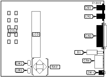
CONNECTIONS | ||||||
|
Function |
Label |
Function |
Label | |||
|
Line out |
CN1 |
Power switch |
SW1 | |||
|
Line in/leased line |
CN2 |
LCD panel lock |
SW2 | |||
|
RS-232/422 |
CN3 |
Voice/data |
SW3 | |||
|
DC power |
CN4 |
LCD panel navigation |
NAV | |||
|
Volume |
R1 | |||||
|
DIAGNOSTIC LED(S) | |||
|
LED |
Color |
Status |
Condition |
|
MR |
Yellow |
On |
Power is on |
|
MR |
Yellow |
Off |
Power is off |
|
TR |
Yellow |
On |
DTR signal is high |
|
TR |
Yellow |
Off |
DTR signal is low |
|
RTS |
Yellow |
On |
RTS signal is high |
|
RTS |
Yellow |
Off |
RTS signal is low |
|
CTS |
Yellow |
On |
CTS signal is high |
|
CTS |
Yellow |
Off |
CTS signal is low |
|
AA |
Yellow |
On |
Auto-answer enabled |
|
AA |
Yellow |
Off |
Auto-answer disabled |
|
AA |
Yellow |
Blinking |
Phone is ringing |
|
RL |
Yellow |
On |
Error correction enabled |
|
RL |
Yellow |
Off |
Error correction disabled |
|
RL |
Yellow |
Blinking |
Error detected |
|
RD |
Yellow |
Blinking |
Modem is receiving data |
|
RD |
Yellow |
Off |
Modem is not receiving data |
|
SD |
Yellow |
Blinking |
Modem is transmitting data |
|
SD |
Yellow |
Off |
Modem is not transmitting data |
|
CD |
Yellow |
On |
Carrier signal detected |
|
CD |
Yellow |
Off |
Carrier signal not detected |
|
OH |
Yellow |
On |
Modem is off-hook |
|
OH |
Yellow |
Off |
Modem is on-hook |
Proprietary AT Command Set
|
ANSWER TONE DETECTION | ||
|
Type: |
Configuration | |
|
Format: |
AT [cmds] %In [cmds] | |
|
Description: |
Controls answer tone detection | |
|
Command |
Function | |
|
%I0 |
Answer tone detection enabled | |
|
%I1 |
Answer tone detection disabled | |
|
AUTO REDIAL INTERVAL TIMES | |
|
Type |
Register |
|
Format |
AT [cmds] S19=n [cmds] |
|
Default |
2 |
|
Range |
0-255 |
|
Unit |
Unidentified |
|
Description |
Unidentified |
|
AUTO-RELIABLE FALLBACK CHARACTER | |
|
Type: |
Configuration |
|
Format: |
AT [cmds] %An [cmds] |
|
Default: |
0 |
|
Range: |
0-127 |
|
Unit: |
ASCII |
|
Description: |
Sets the character used as the auto-reliable fallback character. %A0 will disable this function |
|
AUTO-RELIABLE TIME BUFFER CONFIGURATION | |
|
Type: |
Configuration |
|
Format: |
AT [cmds] \Cn [cmds] |
|
Description: |
Controls the handling of incoming data during auto-reliable time period |
|
Command |
Function |
|
í \CO |
Data is discarded |
|
\C1 |
Data is buffered |
|
\C2 |
Data is discarded, resets to \C1 on receipt of autoreliable fallback character |
|
AUTO-RETRAIN | |
|
Type: |
Configuration |
|
Format: |
AT %En |
|
Description: |
Selects auto-retrain mode |
|
Command |
Function |
|
%E0 |
Auto-retrain disabled |
|
%E1 |
Three auto-retrains attempted then hang up for 2400bps and above enabled |
|
í %E2 |
Three auto-retrains attempted then hang up for 2400bps and above enabled |
|
BIT-MAPPED REGISTER S14 | ||
|
Format |
AT [cmds] S14=n [cmds] | |
|
Default: |
136 | |
|
Range: |
0-254 | |
|
Unit: |
Bit-mapped | |
|
Description: |
Controls echo, result codes, result code display, dumb mode, dial mode, dumb modem and answer/originate mode | |
|
Bit |
Value |
Function |
|
0 |
0 |
Not used |
|
1 |
í 01 |
Command echo disabled Command echo enabled |
|
2 |
í 01 |
Result codes enabled Result codes disabled |
|
3 |
0 í 1 |
Display result codes in numeric format Display result codes in verbose format |
|
4 |
í 01 |
Smart mode Dumb mode |
|
5 |
í 01 |
Tone dial enabled Pulse dial enabled |
|
6 |
í 01 |
Smart modem Dumb modem |
|
7 |
0 í 1 |
Answer mode enabled Originate mode enabled |
|
BIT-MAPPED REGISTER S21 | |||||
|
Format: |
AT [cmds] S20=n [cmds] | ||||
|
Default: |
176 | ||||
|
Range: |
0-187 | ||||
|
Description: |
Controls jack type, DSR, DTR, DCD and disconnect options | ||||
|
Bit |
Value |
Function | |||
|
0 |
í 01 |
RJ-11/41S/45S RJ12-12/13 | |||
|
1 |
í 01 |
DSR forced high DSR normal | |||
|
2 |
0 |
Not used | |||
|
4, 3 |
00 01 í 1011 |
Ignore DTR Go to command mode on low DTR Hang up on low DTR Initialize on low DTR | |||
|
5 |
0 í 1 |
DCD forced high Normal operation | |||
|
7, 6 |
00 01 í 10 |
Special disconnect disabled Long space disconnect enabled Clear down disconnect enabled | |||
|
BIT-MAPPED REGISTER S22 | ||
|
Format |
AT [cmds] S22=n [cmds] | |
|
Default: |
118 | |
|
Range: |
0 - 255 | |
|
Unit: |
Bit-mapped. | |
|
Description: |
Controls volume and speaker settings, result codes, and make/break pulse ratio | |
|
Bit |
Value |
Function |
|
1, 0 |
00 01 í 1011 |
Lowest volume setting Low volume setting Medium volume setting Highest volume setting |
|
3, 2 |
00 í 0110 11 |
Speaker disabled Speaker enabled until carrier signal detected Speaker enabled Speaker enabled until carrier signal detected, but disable during dialing |
|
6, 5 ,4 |
000 001 010 011 í 100 |
Numeric result codes enabled Verbose result codes enabled Dialtone detection enabled Busy tone detection enabled Busy and dialtone detection enabled |
|
7 |
í 01 |
39/61ms at 10pps (North America) 33/67ms at 10pps (Europe) |
|
BIT-MAPPED REGISTER S24 | |||||
|
Format: |
AT [cmds] S24=n [cmds] | ||||
|
Default: |
0 | ||||
|
Range: |
0-7 | ||||
|
Description: |
Controls V.25bis options | ||||
|
Bit |
Value |
Function | |||
|
0 |
í 01 |
V.25bis disabled V.25bis enabled | |||
|
1 |
í 01 |
V.25bis asynchronous enabled V.25bis synchronous enabled | |||
|
2 |
í 01 |
V.25bis HDLC enabled V.25bis bisynchronous enabled | |||
|
BIT-MAPPED REGISTER S27 | |||||
|
Format: |
AT [cmds] S27=n [cmds] | ||||
|
Default: |
0 | ||||
|
Range: |
0-236 | ||||
|
Description: |
Controls synchronous mode, pulse dial speed, clock source, and data protocol | ||||
|
Bit |
Value |
Function | |||
|
2, 1, 0 |
í 000001 010 011 100 |
Asynchronous operation Synchronous mode 1 operation Synchronous mode 2 operation Synchronous mode 3 operation Asynchronous dial | |||
|
3 |
í 01 |
Standard pulse dial enabled Fast pulse dial enabled | |||
|
5, 4 |
í 0001 10 |
Local DCE transmit clock enabled Local DTE transmit clock enabled Remote DCE transmit enabled | |||
|
7, 6 |
í 0001 10 11 |
V.21, V.22, V.32 enabled Bell 103A/212A V.23 back channel V.23 main channel | |||
|
BIT-MAPPED REGISTER S29 | |||||
|
Format: |
AT [cmds] S29=n [cmds] | ||||
|
Default: |
3 | ||||
|
Range: |
31 | ||||
|
Description: |
Controls data bits, parity and stop bits | ||||
|
Bit |
Value |
Function | |||
|
1, 0 |
00 01 10 í 11 |
5 data bits 6 data bits 7 data bits 8 data bits | |||
|
3, 2 |
í 0001 10 11 |
No parity Space parity Even parity Odd parity | |||
|
4 |
í 01 |
1 stop bit 2 stop bits | |||
|
BIT-MAPPED REGISTER S32 | |||||
|
Format: |
AT [cmds] S32=n [cmds] | ||||
|
Default: |
17 | ||||
|
Range: |
0-191 | ||||
|
Description: |
Controls ring, call back security, hardware data security, message working bit, V.32 forward/backward link, &Z/@Z working bit and line used | ||||
|
Bit |
Value |
Function | |||
|
0 |
0 í 1 |
Ring disabled Ring enabled | |||
|
1 |
í 01 |
Call back security disabled Call back security enabled | |||
|
2 |
í 01 |
Hardware data security disabled Hardware data security enabled | |||
|
3 |
í 01 |
Open message working bit Close message working bit | |||
|
4 |
0 í 1 |
V.32 forward/backward link disabled V.32 forward/backward link enabled | |||
|
5 |
í 01 |
&Z working bit enabled @Z working bit enabled | |||
|
7, 6 |
í 0001 10 |
Switched line enabled 2 wire leased line enabled 4 wire leased line enabled | |||
|
BIT-MAPPED REGISTER S34 | |||||
|
Format: |
AT [cmds] S34=n [cmds] | ||||
|
Default: |
0 | ||||
|
Range: |
0-63 | ||||
|
Description: |
Controls V.32 TCM/QAM, DTR dump recognition, RLSD level, asynchronous and soft reset | ||||
|
Bit |
Value |
Function | |||
|
0 |
í 01 |
Enable trellis code modulation Enable quadratic amplitude modulation | |||
|
1 |
í 01 |
Recognize DTR dump in handshaking Ignore DTR dump in handshaking | |||
|
3, 2 |
í 0001 10 11 |
RLSD on at, -43dbm off at -48dbm RLSD on at, -33dbm off at -38dbm RLSD on at, -26dbm off at -31dbm RLSD on at, -16dbm off at -21dbm | |||
|
5, 4 |
í 0001 10 |
Normal AT&F ATZ Quick ATZ.2 Quick AT&F ATZ | |||
|
BIT-MAPPED REGISTER S35 | |||||
|
Format: |
AT [cmds] S35=n [cmds] | ||||
|
Default: |
15 | ||||
|
Range: |
0-232 | ||||
|
Description: |
Controls Power on auto dial | ||||
|
Bit |
Value |
Function | |||
|
3, 2, 1, 0 |
0000 í 1000 |
STN for power on auto dial Power on auto dial disabled | |||
|
5, 4 |
í 0001 10 |
Restore all disabled Switched line simulates leased line enabled Switched line back up enabled | |||
|
6 |
í 01 |
Single phone system enabled Multiple phone systems enabled | |||
|
7 |
í 01 |
Disconnect reset disabled Disconnect reset enabled | |||
|
BIT-MAPPED REGISTER S39 | |||||
|
Format: |
AT [cmds] S39=n [cmds] | ||||
|
Default: |
153 | ||||
|
Range: |
0-253 | ||||
|
Description: |
Controls compression, auto retrain answer tone check, compromise equalizer and detect phase | ||||
|
Bit |
Value |
Function | |||
|
0 |
0 í 1 |
Data compression disabled Data compression enabled | |||
|
2, 1 |
00 í 0110 |
Auto retrain disabled Auto retrain on same speed Auto retrain with speed change | |||
|
4, 3 |
00 01 10 í 11 |
Disabled Transmit only Receive only Transmit and receive | |||
|
5 |
í 01 |
Answer tone check enabled Answer tone check disabled | |||
|
6 |
í 01 |
Compromise equalizer enabled Compromise equalizer disabled | |||
|
7 |
0 í 1 |
Detect phase disabled Detect phase enabled | |||
|
BIT-MAPPED REGISTER S40 | |||||
|
Format: |
AT [cmds] S40=n [cmds] | ||||
|
Default: |
0 | ||||
|
Range: |
0-33 | ||||
|
Description: |
Controls remote access and remote access security | ||||
|
Bit |
Value |
Function | |||
|
0 |
í 01 |
Remote access disabled Remote access enabled | |||
|
4, 3, 2, 1 |
0000 |
Not used | |||
|
5 |
í 01 |
Remote access security disabled Remote access security enabled | |||
|
BIT-MAPPED REGISTER S43 | |||||
|
Format: |
AT [cmds] S43=n [cmds] | ||||
|
Default: |
19 | ||||
|
Range: |
0-155 | ||||
|
Description: |
Controls MNP block size, dictionary size and data buffer | ||||
|
Bit |
Value |
Function | |||
|
1, 0 |
00 01 10 í 11 |
Maximum MNP block size 64 characters Maximum MNP block size 128 characters Maximum MNP block size 192 characters Maximum MNP block size 256 characters | |||
|
2 |
0 |
Not used | |||
|
4, 3 |
00 01 í 1011 |
Maximum dictionary size 512 entries Maximum dictionary size 1024 entries Maximum dictionary size 2048 entries Maximum dictionary size 4048 entries | |||
|
5 |
0 |
Not used | |||
|
7, 6 |
í 0001 10 |
Disable data buffer Set buffer to 4 seconds, 200 characters or SYN character detected then switch to normal connection Data buffer disabled, switch to normal connection | |||
|
BIT-MAPPED REGISTER S44 | |||||
|
Format: |
AT [cmds] S44=n [cmds] | ||||
|
Default: |
0 | ||||
|
Range: |
140 | ||||
|
Description: |
Controls echo, flow control and serial port speed. | ||||
|
Bit |
Value |
Function | |||
|
2 |
í 01 |
On line data echo disabled On line data echo enabled | |||
|
3 |
í 01 |
Modem port flow control disabled Modem port flow control enabled | |||
|
6, 5, 4 |
000 |
Not used | |||
|
7 |
í 01 |
Serial port speed locked Serial port speed follows connection speed | |||
|
BIT-MAPPED REGISTER S45 | |||||
|
Format: |
AT [cmds] S45=n [cmds] | ||||
|
Default: |
101 | ||||
|
Range: |
253 | ||||
|
Description: |
Controls break control, link type, DTE speed and mode | ||||
|
Bit |
Value |
Function | |||
|
2, 1, 0 |
000 001 010 011 100 í 101 |
Enter command mode, do not send break Clear buffer, send break immediately Enter command mode, do not send break Do not clear buffer, send break immediately Enter command mode, do not send break Send break with transmitted data | |||
|
3 |
í 01 |
Stream link enabled Block link enabled | |||
|
4 |
í 01 |
DTE speed follows connect speed DTE speed locked | |||
|
7, 6, 5 |
000 001 010 í 011100 101 110 111 |
Normal mode Direct mode MNP mode Auto reliable mode LAPM mode LAPM with fallback to normal mode LAPM with fallback to MNP mode MNP with fallback to normal mode | |||
|
BIT-MAPPED REGISTER S46 | |||||
|
Format: |
AT [cmds] S46=n [cmds] | ||||
|
Default: |
75 | ||||
|
Range: |
0-238 | ||||
|
Description: |
Controls flow control, ring indicate and result codes | ||||
|
Bit |
Value |
Function | |||
|
2, 1, 0 |
000 001 010 í 011100 101 110 |
Flow control disabled XON/XOFF flow control enabled Unidirectional hardware flow control enabled Bidirectional hardware flow control enabled Unidirectional XON/XOFF flow control enabled CTS low until connect, then CTS unidirectional flow control enabled CTS low until connect, then RTS/CTS flow control enabled | |||
|
3 |
0 í 1 |
Ring indicate after handshaking enabled Ring indicate after handshaking disabled | |||
|
6, 5, 4 |
000 001 010 011 í 100101 110 |
V.42/MNP result code disabled V.42/MNP4 and DTE speed result codes enabled V.42/MNP4 and DCE speed result codes enabled V.42bis/MNP5 and DTE speed result codes enabled V.42bis/MNP5 and DCE speed result codes enabled V.42bis/MNP5 and DTE debug codes enabled V.42bis/MNP5 and DCE debug codes enabled | |||
|
7 |
í 01 |
Flow control character trapped Flow control character passed through | |||
|
BIT-MAPPED REGISTER S53 | |||||
|
Format: |
AT [cmds] S53=n [cmds] | ||||
|
Default: |
56 | ||||
|
Range: |
0-56 | ||||
|
Description: |
Controls ring indicate reset timer, V.25 calling tone and T30 calling tone | ||||
|
Bit |
Value |
Function | |||
|
3, 2, 1, 0 |
í 1000 |
Ring indicate reset timer | |||
|
4 |
0 í 1 |
V.25 calling tone disabled V.25 calling tone enabled | |||
|
5 |
0 í 1 |
T30 calling tone disabled T30 calling tone enabled | |||
|
BREAK SEND | |
|
Type: |
Configuration |
|
Format: |
AT [cmds] \Bn [cmds] |
|
Default: |
3 |
|
Range: |
0-9 |
|
Unit: |
.1 second |
|
Description: |
Sends break to modem |
|
BREAK TYPE | |||
|
Type: |
Configuration | ||
|
Format: |
AT [cmds] \Kn [cmds] | ||
|
Description: |
Configures action of break signal | ||
|
Command |
Break from DTE | ||
|
\K0 |
Online command mode enabled, send no break to remote modem | ||
|
\K1 |
Break sent to remote modem and buffers cleared | ||
|
\K2 |
Online command mode enabled, send no break to remote modem | ||
|
\K3 |
Send break to remote modem immediately | ||
|
\K4 |
Online command mode enabled, send no break to remote modem | ||
|
\K5 |
Send break with transmitted data | ||
|
CALL BACK DELAY TIMER | |
|
Type |
Register |
|
Format |
AT [cmds] S31=n [cmds] |
|
Default |
10 |
|
Range |
0-255 |
|
Unit |
1 second |
|
Description |
Controls call back delay |
|
CALLBACK NUMBER | |
|
Type |
Configuration |
|
Format |
AT [cmds] @Zn=xxx [cmds] |
|
Default |
None |
|
Description |
Stores numbers to be called back during callback operation. N is a memory location from 0-9 and xxx is a combination of the number and up to 49 dial modifiers. |
|
CALLBACK PASSWORD | |
|
Type |
Configuration |
|
Format |
AT [cmds] @Wn=xxxxxxxxxx [cmds] |
|
Default |
None |
|
Range |
A-Z, a-z,0-9 |
|
Unit |
ASCII string |
|
Description |
Stores callback password (n is password and xxxxxxxxxx is up to ten characters) |
|
CALLBACK SECURITY | ||
|
Type: |
Configuration | |
|
Format: |
AT [cmds] @An [cmds] | |
|
Description: |
Modem returns call to previously stored number | |
|
Command |
Function | |
|
í @A0 |
Callback security disabled | |
|
@A1 |
Callback security enabled | |
|
CALL BACK SECURITY DELAY | |
|
Type |
Configuration |
|
Format |
AT [cmds] @Dn [cmds] |
|
Default |
30 |
|
Range |
1-255 |
|
Unit |
1 second |
|
Description |
Sets length of wait before dialing stored callback security phone number |
|
CARRIER DETECT TIMER | |
|
Type |
Register |
|
Format |
AT [cmds] S17=n [cmds] |
|
Default |
10 |
|
Range |
0-255 |
|
Unit |
Unidentified |
|
Description |
Unidentified |
|
CLOSING MESSAGE | |
|
Type |
Configuration |
|
Format |
AT [cmds] @Gxxx [cmds] |
|
Default |
THANK YOU! YOU WILL BE CALLED BACK! |
|
Range |
Up to 60 characters |
|
Unit |
ASCII |
|
Description |
Stores a closing message |
|
CONNECTION PASSWORD SECURITY | ||
|
Type: |
Configuration | |
|
Format: |
AT [cmds] @En [cmds] | |
|
Description: |
Requires correct password to be included in dial command string | |
|
Command |
Function | |
|
í @E0 |
Password security disabled | |
|
@E1 |
Password security enabled | |
|
COMPRESSION | |
|
Type: |
Configuration |
|
Format: |
AT %Cn |
|
Description: |
Selects data compression |
|
Command |
Function |
|
%C0 |
Data compression disabled |
|
í %C1 |
MNP5 and V.42bis enabled |
|
CONNECT MODE | |
|
Type: |
Configuration |
|
Format: |
AT [cmds] \Nn [cmds] |
|
Description: |
Sets connect mode |
|
Command |
Function |
|
\N0 |
Normal mode enabled |
|
\N1 |
Direct mode enabled |
|
\N2 |
MNP reliable mode only enabled |
|
í \N3 |
V.42 and MNP modes enabled |
|
\N4 |
V.42bis and V.42 modes enabled |
|
CONNECTION PASSWORD | |
|
Type |
Configuration |
|
Format |
AT [cmds] @Pxxxxxxxxx [cmds] |
|
Default |
None |
|
Range |
A-Z,a-z,0-9,*,# |
|
Unit |
ASCII string |
|
Description |
Stores password required by command string password security option of up to nine characters |
|
CONNECTION SPEED UPPER LIMIT | |
|
Type: |
Immediate |
|
Format: |
AT [cmds] %Bn [cmds] |
|
Description: |
Selects the current DCE speed. |
|
Command |
Function |
|
í %B0 |
Line speed sets maximum serial port speed |
|
%B300 |
300bps |
|
%B600 |
600bps |
|
%B1200 |
1200bps |
|
%B2400 |
2400bps |
|
%B4800 |
4800bps |
|
%B7200 |
7200bps |
|
%B9600 |
9600bps |
|
%B12000 |
12.0Kbps |
|
%B16800 |
16.8Kbps |
|
%B14400 |
14.4Kbps |
|
%B19200 |
19.2Kbps |
|
%B21600 |
21.6Kbps |
|
%B24000 |
24.0Kbps |
|
%B26400 |
26.4Kbps |
|
%B28800 |
28.8Kbps |
|
DIAL TONE DETECT | |
|
Type: |
Configuration |
|
Format: |
AT [cmds] W [cmds] |
|
Description: |
Requires a continuous three second dial tone before dialing |
|
DISPLAY CALLBACK SETTINGS | ||
|
Type: |
Immediate | |
|
Format: |
AT [cmds] @Vn [cmds] | |
|
Description: |
Displays passwords, messages and phone numbers stored in memory | |
|
Command |
Function | |
|
@V0 |
Display stored callback security passwords | |
|
@V1 |
Display stored callback security phone numbers | |
|
@V2 |
Display opening and closing messages | |
|
DISPLAY PASSWORDS | |
|
Type: |
Immediate |
|
Format: |
AT [cmds] @Fn [cmds] |
|
Description: |
Displays callback security and remote access passwords |
|
DTR DELAY | |
|
Type |
Register |
|
Format |
AT [cmds] S25=n [cmds] |
|
Default |
5 |
|
Range |
0-255 |
|
Unit |
1 second |
|
Description |
Sets length of time modem ignores DTR change |
|
DUMB MODE | ||
|
Type: |
Configuration | |
|
Format: |
AT [cmds] @In [cmds] | |
|
Description: |
Controls smart and dumb modes | |
|
Command |
Function | |
|
í @I0 |
Smart mode | |
|
@I1 |
Dumb mode | |
|
FLOW CONTROL TYPE | |
|
Type: |
Configuration |
|
Format: |
AT [cmds] \Qn [cmds] |
|
Description: |
Sets type of flow control used by modem |
|
Command |
Function |
|
\Q0 |
Flow control disabled |
|
\Q1 |
XON/XOFF flow control enabled |
|
\Q2 |
CTS flow control to DTE enabled |
|
í \Q3 |
RTS/CTS flow control enabled |
|
FLOW CONTROL | |
|
Type: |
Configuration |
|
Format: |
AT [cmds] \Gn [cmds] |
|
Description: |
Selects modem port flow control |
|
Command |
Function |
|
í \G0 |
Flow control disabled |
|
\G1 |
Flow control enabled |
|
HANG UP DELAY | |
|
Type |
Register |
|
Format |
AT [cmds] S38=n [cmds] |
|
Default |
0 |
|
Range |
0-255 |
|
Unit |
Unidentified |
|
Description |
Sets time before forced hang up, n=255 disables |
|
INACTIVITY TIMER | |
|
Type: |
Configuration |
|
Format: |
AT [cmds] \Tn [cmds] |
|
Default: |
0 |
|
Range: |
0-255 |
|
Unit: |
1 minute |
|
Description: |
Sets the length of time that the modem does not receive information before it disconnects |
|
INACTIVITY TIMER | |
|
Type |
Register |
|
Format |
AT [cmds] S47=n [cmds] |
|
Default |
0 |
|
Range |
0-255 |
|
Unit |
Unidentified |
|
Description |
Sets time modem waits before disconnecting |
|
LEASED LINE DIALUP BACKUP TIMES | |
|
Type: |
Register |
|
Format: |
AT [cmds] S13=n [cmds] |
|
Default: |
0 |
|
Range: |
0-255 |
|
Unit: |
Unidentified |
|
Description: |
After leased line failure, modem attempts to reconnect after specified delay |
|
LEASED LINE DIALUP BACKUP TIMER | |
|
Type |
Register |
|
Format |
AT [cmds] S15=n [cmds] |
|
Default |
5 |
|
Range |
0-255 |
|
Unit |
Unidentified |
|
Description |
Unidentified |
|
LEASED LINE RETRY | |
|
Type |
Configuration |
|
Format |
AT [cmds] -Bn [cmds] |
|
Range |
Unidentified |
|
Unit |
Retries |
|
Description |
Controls the number of times a leased line connection is attempted |
|
LINE SIGNAL LEVEL | |
|
Type: |
Immediate |
|
Format: |
AT [cmds] %L [cmds] |
|
Description: |
Returns received line signal level |
|
LEASED LINE TRANSMIT LEVEL | |
|
Type |
Register |
|
Format |
AT [cmds] S51=n [cmds] |
|
Default |
10 |
|
Range |
0-31 |
|
Unit |
Unidentified |
|
Description |
Sets leased line transmit level |
|
LINE TYPE | ||
|
Type: |
Configuration | |
|
Format: |
AT [cmds] @Yn [cmds] | |
|
Description: |
Selects line type | |
|
Command |
Function | |
|
í @Y0 |
Switched line operation | |
|
@Y1 |
Switched line operation emulates leased line operation | |
|
@Y2 |
Leased line with switched line backup | |
|
LOCK DCE | ||
|
Type: |
Configuration | |
|
Format: |
AT [cmds] %Hn [cmds] | |
|
Description: |
Controls DCE speed | |
|
Command |
Function | |
|
%H0 |
DCE speed not locked | |
|
%H1 |
DCE speed locked | |
|
LOCK SERIAL PORT | |
|
Type: |
Configuration |
|
Format: |
AT [cmds] \Jn [cmds] |
|
Description: |
Sets operation of serial port speed |
|
Command |
Function |
|
í \J0 |
Serial speed locked |
|
\J1 |
Serial speed follows connect speed |
|
MAXIMUM BLOCK SIZE FOR TRANSMISSION | |
|
Type: |
Configuration |
|
Format: |
AT [cmds] \An [cmds] |
|
Description: |
Sets the maximum transmittable block size |
|
Command |
Function |
|
\A0 |
MNP block size is 64 characters |
|
\A1 |
MNP block size is 128 characters |
|
\A2 |
MNP block size is 192 characters |
|
í \A3 |
MNP block size is 256 characters |
|
OPENING MESSAGE | |
|
Type |
Configuration |
|
Format |
AT [cmds] @Oxxx [cmds] |
|
Default |
PLEASE ENTER CALL BACK PASSWORD |
|
Range |
Up to 60 characters |
|
Unit |
ASCII string |
|
Description |
Stores an opening message |
|
PROTOCOL | ||
|
Type: |
Configuration | |
|
Format: |
AT [cmds] -Vn [cmds] | |
|
Description: |
Controls protocol used | |
|
Command |
Function | |
|
-V0 |
V.34 auto | |
|
-V1 |
V.FC auto | |
|
-V3 |
V.32bis auto | |
|
-V4 |
V.34/V.FC/V.32bis | |
|
-V5 |
V.34 only | |
|
-V6 |
V.FC only | |
|
-V7 |
V.32bis only | |
|
PROTOCOL | ||
|
Type: |
Register | |
|
Format: |
AT [cmds] S54=n [cmds] | |
|
Description: |
Controls protocol used | |
|
Command |
Function | |
|
í S54=0 |
V.34 auto mode | |
|
S54=1 |
V.FC auto mode | |
|
S54=3 |
V.32bis auto mode | |
|
S54=4 |
V.34, V.FC and V.32bis | |
|
S54=5 |
V.FC and V.32bis | |
|
S54=6 |
V.34 only | |
|
S54=7 |
V.FC only | |
|
S54=8 |
V.32bis only | |
|
REDIAL | |
|
Type |
Configuration |
|
Format |
AT [cmds] N=n [cmds] |
|
Default |
0 |
|
Range |
0-15 |
|
Unit |
Redials |
|
Description |
Sets number of redials attempted if busy signal received |
|
REDIAL INTERVAL | |
|
Type |
Configuration |
|
Format |
AT [cmds] N5=n [cmds] |
|
Default |
1 |
|
Range |
0-255 |
|
Unit |
2 seconds |
|
Description |
Controls time between redials |
|
REDIAL LIMIT | |
|
Type |
Register |
|
Format |
AT [cmds] S49=n [cmds] |
|
Default |
15 |
|
Range |
Unidentified |
|
Unit |
Unidentified |
|
Description |
Sets maximum number of redials |
|
REDIAL ORDER | |
|
Type |
Configuration |
|
Format |
AT [cmds] -Z=nnn [cmds] |
|
Unit |
Phone number memory location |
|
Description |
Controls order in which stored numbers are dialed -Z? displays order |
|
REMOTE ACCESS | ||
|
Type: |
Configuration | |
|
Format: |
AT [cmds] *En [cmds] | |
|
Description: |
Controls remote access operation | |
|
Command |
Function | |
|
í *E0 |
Remote access disabled | |
|
*E1 |
Remote access enabled | |
|
REMOTE ACCESS ATTENTION CHARACTER | |
|
Type |
Register |
|
Format |
AT [cmds] S41=n [cmds] |
|
Default |
42 |
|
Range |
0-255 |
|
Unit |
ASCII |
|
Description |
Selects the remote access attention character |
|
REMOTE ACCESS PASSWORD | |
|
Type |
Configuration |
|
Format |
AT [cmds] *Pxxxxxxxxx |
|
Default |
None |
|
Range |
Up to nine characters |
|
Unit |
ASCII printable characters |
|
Description |
Stores remote access password |
|
REPORT SIGNAL QUALITY | |
|
Type: |
Immediate |
|
Format: |
AT [cmds] %Q [cmds] |
|
Description: |
Reports signal quality |
|
RESULT CODE FORMAT | ||
|
Type: |
Configuration | |
|
Format: |
AT [cmds] \Vn [cmds] | |
|
Description: |
Selects which result codes are displayed | |
|
Command |
Function | |
|
\V0 |
Connect speed result codes enabled | |
|
\V1 |
Connect speed and V.42/MNP result codes enabled | |
|
\V2 |
Connect speed, V.42/MNP and data compression result codes enabled | |
|
\V3 |
Connect speed, V.42/MNP and data compression result codes enabled | |
|
\V4 |
Connect speed, V.42/MNP and data compression result codes enabled | |
|
RINGER | ||
|
Type: |
Configuration | |
|
Format: |
AT [cmds] @Bn [cmds] | |
|
Description: |
Controls ring signal passthrough to modem speaker | |
|
Command |
Function | |
|
@B0 |
Ringer disabled | |
|
í @B1 |
Ringer enabled | |
|
RTS TO CTS DELAY | |
|
Type |
Register |
|
Format |
AT [cmds] S26=n [cmds] |
|
Default |
0 |
|
Range |
0-255 |
|
Unit |
.1 second |
|
Description |
Sets delay after receipt of RTS signal until CTS forced high |
|
SWITCHED LINE TRANSMIT LEVEL | |
|
Type |
Register |
|
Format |
AT [cmds] S50=n [cmds] |
|
Default |
10 |
|
Range |
0-15 |
|
Unit |
Unidentified |
|
Description |
Sets switched line transmit level |
|
SERIAL PORT | |||||
|
Format: |
AT [cmds] S28=n [cmds] | ||||
|
Default: |
113 | ||||
|
Range: |
0-243 | ||||
|
Description: |
Controls serial port options, parity and data bits | ||||
|
Bit |
Value |
Function | |||
|
4, 3, 2, 1, 0 |
00000 00001 00010 00011 00100 00101 00110 00111 01000 01001 01010 01011 01100 01101 01110 01111 10000 í 1000110010 10011 |
Lock serial port at 75bps Lock serial port at 110bps Lock serial port at 300bps Lock serial port at 600bps Lock serial port at 1200bps Lock serial port at 2400bps Lock serial port at 4800bps Lock serial port at 7200bps Lock serial port at 9600bps Lock serial port at 12.0Kbps Lock serial port at 14.4Kbps Lock serial port at 16.8Kbps Lock serial port at 19.2Kbps Lock serial port at 21.6Kbps Lock serial port at 24.0Kbps Lock serial port at 26.4Kbps Lock serial port at 28.8Kbps Lock serial port at 38.4Kbps Lock serial port at 57.6Kbps Lock serial port at 11.52Kbps | |||
|
6, 5 |
00 01 10 í 11 |
Even parity Space parity Odd parity No parity | |||
|
7 |
í 01 |
8 data bits 7 data bits | |||
|
SERIAL PORT SPEED | ||
|
Type: |
Register | |
|
Format: |
AT [cmds] S52n [cmds] | |
|
Description: |
Controls serial port speed | |
|
Command |
Function | |
|
í S52=0 |
Serial port speed follows connect speed | |
|
S52=1 |
Lock serial port at 110bps | |
|
S52=2 |
Lock serial port at 300bps | |
|
S52=3 |
Lock serial port at 600bps | |
|
S52=4 |
Lock serial port at 1200bps | |
|
S52=5 |
Lock serial port at 2400bps | |
|
S52=6 |
Lock serial port at 4800bps | |
|
S52=7 |
Lock serial port at 7200bps | |
|
S52=8 |
Lock serial port at 9600bps | |
|
S52=9 |
Lock serial port at 12.0Kbps | |
|
S52=10 |
Lock serial port at 14.4Kbps | |
|
S52=11 |
Lock serial port at 16.8Kbps | |
|
S52=12 |
Lock serial port at 19.2Kbps | |
|
S52=13 |
Lock serial port at 21.6Kbps | |
|
S52=14 |
Lock serial port at 24.0Kbps | |
|
S52=15 |
Lock serial port at 26.4Kbps | |
|
S52=16 |
Lock serial port at 28.8Kbps | |
|
S52=17 |
Lock serial port at 38.4Kbps | |
|
S52=18 |
Lock serial port at 57.6Kbps | |
|
S52=19 |
Lock serial port at 11.52Kbps | |
|
SERVICE CLASS | |||||
|
Format: |
AT [cmds] S33=n [cmds] | ||||
|
Default: |
0 | ||||
|
Range: |
192 | ||||
|
Description: |
Controls MNP link and second channel | ||||
|
Bit |
Value |
Function | |||
|
6 |
í 01 |
MNP synchronous link enabled MNP asynchronous link enabled | |||
|
7 |
í 01 |
Second channel disabled Second channel enabled | |||
|
TEST MODES | ||
|
Format |
AT [cmds] S16=n [cmds] | |
|
Default: |
0 | |
|
Range: |
0-255 | |
|
Unit: |
Bit-mapped | |
|
Description: |
Controls loopback tests, analog, digital, remote digital, and self tests | |
Note: Bit 3 is read only | ||
|
Bit |
Value |
Function |
|
0 |
í 01 |
Local analog loopback disabled Local analog loopback in enabled |
|
1 |
í 01 |
Local digital loopback disabled Local digital loopback in enabled |
|
2 |
í 01 |
Local digital loopback disabled Local digital loopback in enabled |
|
3 |
í 01 |
Modem not in remote digital loopback Remote digital loopback in progress |
|
4 |
í 01 |
Remote digital loopback disabled Remote digital loopback enabled |
|
5 |
í 01 |
Remote digital loopback w/ self-test disabled Remote digital loopback w/ self-test enabled |
|
6 |
í 01 |
Local analog loopback enabled Local analog loopback disabled |
|
7 |
í 01 |
Remote digital loopback enabled Remote digital loopback disabled |
|
V.25bis MODES | ||
|
Type: |
Configuration | |
|
Format: |
AT [cmds] *Cn [cmds] | |
|
Description: |
Selects type of V.25bis operation | |
|
Command |
Function | |
|
*C0 |
V.25bis disabled | |
|
*C1 |
V.25bis asynchronous enabled | |
|
*C2 |
V.25bis bi-synchronous enabled | |
|
*C3 |
V.25bis HDLC enabled | |
|
V.42bis MAXIMUM STRING LENGTH | |
|
Type: |
Register |
|
Format: |
AT [cmds] S42=n [cmds] |
|
Default: |
16 |
|
Range: |
0-255 |
|
Unit: |
Unidentified |
|
Description: |
Selects string size for V.42bis compression |
|
WAIT FOR CONNECTION PASSWORD | |
|
Type |
Register |
|
Format |
AT [cmds] S48=n [cmds] |
|
Default |
15 |
|
Range |
0-255 |
|
Unit |
1 second |
|
Description |
Sets length of wait for connection password after connection |
|
XON/XOFF PASS-THROUGH | |
|
Type: |
Configuration |
|
Format: |
AT [cmds] \Xn [cmds] |
|
Description: |
Selects whether XON/XOFF signals are sent to remote modem |
|
Command |
Function |
|
í \X0 |
XON/XOFF signals trapped by local modem |
|
\X1 |
XON/XOFF passed through local modem |
|
S REGISTERS | ||
|
Register |
Default |
Function |
|
S49 |
15 |
Redial limit |
|
S50 |
10 |
Switched line transmit level |
|
S51 |
10 |
Leased line transmit level |