BOCA RESEARCH, INC.
SOUND EXPRESSION (SE34SRS),
SOUND EXPRESSION (SE34SVD)
|
Card Type |
Sound/Modem card |
|
Chip Set |
Unidentified |
|
Maximum Onboard Memory |
Unidentified |
|
I/O Options |
Game/MIDI port, CD-ROM interface - IDE, Audio in - CD-ROM (3), speaker, line out, line in, microphone in, telephone jack |
|
Maximum Modem Rate |
28.8Kbps |
|
Maximum Fax Rate |
14.4Kbps |
|
Data Modulation Protocol |
Bell 103A/212A ITU-T V.22, V.22bis, V.32, V.32bis, V.34 Rockwell V.FC |
|
Fax Modulation Protocol |
ITU-T V.17, V.21CH2, V.27ter, V.29 |
|
Error Correction/Compression |
MNP5, V.42, V.42bis |
|
Fax Class |
Class I & II |
|
Data Bus |
16-bit ISA |
|
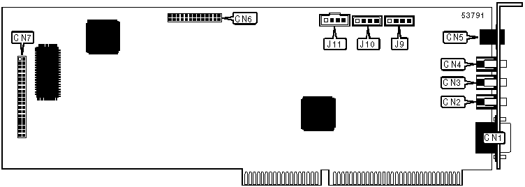
CONNECTIONS | ||||||
|
Function |
Location |
Function |
Location | |||
|
Game/MIDI port |
CN1 |
Wavetable |
CN6 | |||
|
Speaker |
CN2 |
CD-ROM interface - IDE |
CN7 | |||
|
Line out |
CN3 |
Audio in - CD-ROM (Mitsumi) |
J9 | |||
|
Line in |
CN4 |
Audio in - CD-ROM (Panasonic) |
J10 | |||
|
RJ-11 telephone jack |
CN5 |
Audio in - CD-ROM (Sony/IDE) |
J11 | |||
|
SUPPORTED COMMAND SET |
|
Basic AT Commands |
|
AT, ‘+++’, ‘comma’, A/ |
|
A, B, C, E, H, L, M, O, Q, R, S, T, U, V, W, X, Y, Z |
|
&C, &F, &P, &Q, &R, &S, &T, &V, &W, &Y, &Z |
|
Extended AT Commands |
|
\A, \B |
|
%C, %E, %L, %Q |
|
S Registers |
|
S0, S1, S2, S3, S4, S5, S6, S7, S8, S9, S10, S11, S12, S14, S16, S18, S21, S22, S23, S24, S25, |
|
S26, S27, S28, S29, S30,S31, S32, S33, S36, S38, S39, S40, S41, S46, S48, S82, S86, S91, S92, |
|
S95 |
|
Special Commands |
|
+MS?, +MS |
|
Note: See MHI Help File for full command documentation. |
Proprietary AT Command Set
|
DIAL | |
|
Type: |
Immediate |
|
Format: |
AT [cmds] D<#> [cmds] |
|
Description: |
Dials telephone number according to any modifiers included in the string |
|
Note: |
Any combination of modifiers can be used to produce the desired dial functions in sequence. |
|
Command |
Function |
|
D |
Dial |
|
DL |
Re-dial last number |
|
DP |
Pulse dialing enabled |
|
DS=n |
Dial stored telephone number n |
|
DT |
Tone dialing enabled/Pulse dialing disabled |
|
DW |
Dialing resumed following dial tone detection |
|
D, |
Dialing paused for amount of time specified in S8 register |
|
D! |
Flash function initiated. Modem commanded to go off-hook for specified time before returning on-hook. |
|
D@ |
Wait for Quite Answer function enabled. Modem waits until a "quiet answer," a ring-back signal followed by silence up to the time specified in S7, is received prior to executing the rest of the dial string. |
|
D; |
Modem returned to idle state after dialing. The semicolon can only be placed at the end of the dial command. |
|
D^ |
Disable dialing code. |
|
REPORT INFORMATION | |
|
Type: |
Immediate |
|
Format: |
AT [cmds] In [cmds] |
|
Description: |
Displays information requested |
|
Command |
Function |
|
I0 |
Reports product ID |
|
I1 |
Reports checksum |
|
I2 |
Tests and reports ROM checksum |
|
I3 |
Reports firmware revision |
|
I4 |
Reports OEM-defined identifier string. |
|
I5 |
Reports country code |
|
I6 |
Reports modem data pump model |
|
AUTO-MODE DETECTION | |
|
Type: |
Configuration |
|
Format: |
AT [cmds] Nn [cmds] |
|
Description: |
Selects various options for the automatic detection and negotiation of protocols during the handshake process if the modem is communicating with a remote modem of dissimilar speed. |
|
Command |
Function |
|
N0 |
Auto-mode detection disabled |
|
í N1 |
Permits handshaking at any speed supported by both modems. |
|
DATA TERMINAL READY (DTR) | |||||
|
Type: |
Configuration | ||||
|
Format: |
AT [cmds] &Dn [cmds] | ||||
|
Description: |
Selects modem response to DTR | ||||
Note: The action each variant of &D causes depends on the setting of &Q | |||||
|
&Q Setting |
&D0 |
&D1 |
&D2 |
&D3 | |
|
í &Q0, &Q5, &Q6 |
Command 0 |
Command 3 |
Command 2 |
Command 4 | |
|
&Q1, &Q4 |
Command 1 |
Command 3 |
Command 2 |
Command 4 | |
|
&Q2, &Q3 |
Command 2 |
Command 2 |
Command 2 |
Command 2 | |
|
Command |
Function | ||||
|
Command 0 |
Modem does not respond to DTR | ||||
|
Command 1 |
Modem disconnects (hangs up) after DTR goes off; Auto-Answer not affected | ||||
|
í Command 2 |
Modem goes to command mode and disconnects (hangs up) after DTR goes off; Auto-Answer is disabled. | ||||
|
Command 3 |
Asynchronous escape sequence | ||||
|
Command 4 |
Modem does a soft reset | ||||
|
FLOW CONTROL | |
|
Type: |
Configuration |
|
Format: |
AT [cmds] &Kn [cmds] |
|
Description: |
Enables flow control options |
|
Command |
Function |
|
&K0 |
Flow control disabled |
|
í &K3 |
RTS/CTS flow control enabled |
|
&K4 |
XON/XOFF flow control enabled |
|
&K5 |
Enable transport XON/XOFF |
|
&K6 |
Enable both RTS/CTS and XON/XOFF |
|
BREAK TYPE | ||||
|
Type: |
Configuration | |||
|
Format: |
AT [cmds] \Kn [cmds] | |||
|
Description: |
Configures action of break signal | |||
|
Command |
Break from DTE |
Break from DTE during Direct Mode |
Break received from remote modem | |
|
\K0 |
Online command mode enabled, send no break to remote modem |
Break sent to remote modem and command entered |
Buffers cleared, break sent to DTE | |
|
\K1 |
Break sent to remote modem and buffered cleared |
Break sent to remote modem and command entered |
Buffers cleared, break sent to DTE | |
|
\K2 |
Online command mode enabled, send no break to remote modem |
Send break with transmitted data |
Break sent immediately to DTE | |
|
\K3 |
Send break to remote modem immediately |
Break sent to remote modem and command entered |
Break sent immediately to DTE | |
|
\K4 |
Online command mode enabled, send no break to remote modem |
Send break with transmitted data |
Break sent with received data to the DTE | |
|
í \K5 |
Send break with transmitted data |
Send break with transmitted data |
Break sent with received data to the DTE | |
|
CONNECT MODE | |
|
Type: |
Configuration |
|
Format: |
AT [cmds] \Nn [cmds] |
|
Description: |
Controls the type of connection the modem will operate in |
|
Command |
Function |
|
\N0 |
Normal mode enabled |
|
\N1 |
Direct mode enabled |
|
\N2 |
MNP reliable mode enabled |
|
\N3 |
Auto-reliable mode or MNP auto-reliable mode enabled |
|
\N4 |
V.42 reliable mode enabled |
|
\N5 |
V.42 auto-reliable mode or MNP auto-reliable mode enabled |
|
DCE LINE SPEED | |
|
Type: |
Register |
|
Format |
AT [cmds] S37=n [cmds] |
|
Description: |
Sets the maximum allowable data exchange rate attempted during handshake process. |
|
Command |
Function |
|
í S37=0 |
Speed of last connection |
|
S37=1-3 |
300bps |
|
S37=4 |
Reserved |
|
S37=5 |
1200bps |
|
S37=6 |
2400bps |
|
S37=7 |
V.23 mode |
|
S37=8 |
4800bps |
|
S37=9 |
9600bps |
|
S37=10 |
12.0Kbps |
|
S37=11 |
14.4Kbps |
|
S37=12 |
7200bps |
RESULT CODES
|
BASIC RESULT CODES | |||
|
Numeric |
Verbose |
Wn |
Function |
|
0 |
OK |
W0 |
Modem has successfully executed the previous command and has returned to the on-line command state. |
|
1 |
CONNECT |
W0 |
Connection established at unspecified rate. |
|
2 |
RING |
W0 |
Incoming ring detected. |
|
3 |
NO CARRIER |
W0 |
Carrier signal lost or no connection established. |
|
4 |
ERROR |
W0 |
Last command issued was not valid. |
|
5 |
CONNECT 1200 |
W0 |
Connection established at 1200bps. |
|
6 |
NO DIALTONE |
W0 |
No dial tone was detected within the time allotted by S7. |
|
7 |
BUSY |
W0 |
A busy tone was detected after dialing. |
|
8 |
NO ANSWER |
W0 |
No quiet answer (ring-back followed by silence) was detected. |
|
9 |
CONNECT 600 |
WO |
Connection established at 600bps |
|
10 |
CONNECT 2400 |
W0 |
Connection established at 2400bps. |
|
11 |
CONNECT 4800 |
W0 |
Connection established at 4800bps. |
|
12 |
CONNECT 9600 |
W0 |
Connection established at 9600bps. |
|
13 |
CONNECT 7200 |
WO |
Connected as data modem during answer. |
|
14 |
CONNECT 12000 |
WO |
Connection established at 12000bps. |
|
15 |
CONNECT 14400 |
W0 |
Connection established at 14.4K bps. |
|
16 |
CONNECT 19200 |
W0 |
Connection established at 19.2K bps. |
|
17 |
CONNECT 38400 |
W0 |
Connection established at 38.4K bps. |
|
18 |
CONNECT 57600 |
W0 |
Connection established at 57.6K bps. |
|
19 |
CONNECT 115200 |
W0 |
Connection established at 115.2K bps. |
|
BASIC RESULT CODES (cont'd) | |||
|
Numeric |
Verbose |
Wn |
Function |
|
22 |
CONNECT 75/1200 |
W0 |
Connection established at transmit 75/receive 1200bps. |
|
23 |
CONNECT 1200/75 |
W0 |
Connection established at transmit 1200/receive 75bps. |
|
24 |
DELAYED |
WO |
Connection fails and number dialed is "delayed" due to country blacklisting. |
|
32 |
BLACKLISTED |
WO |
Connection failed and the number dialed is considered "blacklisted" |
|
33 |
FAX |
W0 |
Fax connection established. |
|
35 |
DATA |
W0 |
Data connection established. |
|
EXTENDED RESULT CODES | |||
|
Numeric |
Verbose |
Wn |
Function |
|
40 |
CARRIER 300 |
W1 |
Carrier signal at 300bps is detected. |
|
44 |
CARRIER 1200/75 |
W1 |
Carrier signal at transmit 1200/receive 75bps is detected. |
|
45 |
CARRIER 75/1200 |
W1 |
Carrier signal at transmit 1200/receive 75bps is detected. |
|
46 |
CARRIER 1200 |
W1 |
Carrier signal at 1200bps is detected. |
|
47 |
CARRIER 2400 |
W1 |
Carrier signal at 2400bps is detected. |
|
48 |
CARRIER 4800 |
W1 |
Carrier signal at 4800bps is detected. |
|
49 |
CARRIER 7200 |
W1 |
Carrier signal at 7200bps is detected. |
|
50 |
CARRIER 9600 |
W1 |
Carrier signal at 9600bps is detected. |
|
51 |
CARRIER 12000 |
W1 |
Carrier signal at 12.0K bps is detected. |
|
52 |
CARRIER 14400 |
W1 |
Carrier signal at 14.4K bps is detected. |
|
53 |
CARRIER 16800 |
W1 |
Carrier signal at 16.8K bps is detected. |
|
54 |
CARRIER 19200 |
W1 |
Carrier signal at 19.2K bps is detected. |
|
55 |
CARRIER 21600 |
W1 |
Carrier signal at 21.6K bps is detected. |
|
56 |
CARRIER 24000 |
W1 |
Carrier signal at 24.0K bps is detected. |
|
57 |
CARRIER 26400 |
W1 |
Carrier signal at 26.4K bps is detected. |
|
58 |
CARRIER 28800 |
W1 |
Carrier signal at 28.8K bps is detected. |
|
59 |
CONNECT 16800 |
W0 |
Connection established at 16.8K bps. |
|
61 |
CONNECT 21600 |
W0 |
Connection established at 21.6K bps. |
|
62 |
CONNECT 24000 |
W0 |
Connection established at 24.0K bps. |
|
63 |
CONNECT 26400 |
W0 |
Connection established at 26.4K bps. |
|
64 |
CONNECT 28800 |
W0 |
Connection established at 28.8K bps. |
|
66 |
COMPRESSION: CLASS 5 |
W1 |
MNP Class 5 data compression was negotiated. |
|
67 |
COMPRESSION: V.42BIS |
W1 |
V.42bis data compression was negotiated. |
|
69 |
COMPRESSION: NONE |
W1 |
No data compression was negotiated. |
|
70 |
PROTOCOL: NONE |
W1 |
No protocol was negotiated. |
|
77 |
PROTOCOL: LAP-M |
W1 |
V.42 LAPM error-control was negotiated. |
|
80 |
PROTOCOL: ALT |
W1 |
MNP error-control was negotiated. |
|
81 |
PROTOCOL: ALT-CELLULAR |
W1 |
Modem connected in the MNP10 mode. |