UNIDENTIFIED
P5
|
Processor |
Pentium |
|
Processor Speed |
60/66MHz |
|
Chip Set |
Unidentified |
|
Max. Onboard DRAM |
512MB |
|
Cache |
64/256/1024KB |
|
BIOS |
Award |
|
Dimensions |
300mm x 254mm |
|
I/O Options |
32-bit PCI slots (4) |
|
NPU Options |
None |
|
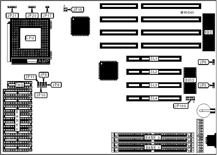
CONNECTIONS |
|||
|
Purpose |
Location |
Purpose |
Location |
|
External battery |
JP3 |
Power LED & keylock |
JP21 |
|
Reset switch |
JP17 |
Interrupt feature connector |
JP100 |
|
Speaker |
JP20 |
32-bit PCI slots |
SL1 - SL4 |
|
USER CONFIGURABLE SETTINGS |
|||
|
Function |
Jumper |
Position |
|
|
» |
BIOS type select 5V |
JP6 |
pins 2 & 3 closed |
|
|
BIOS type select 12V |
JP6 |
pins 1 & 2 closed |
|
» |
CPU speed select 60MHz |
JP15 |
pins 2 & 4 closed |
|
|
CPU speed select 66MHz |
JP15 |
pins 1 & 3, 2 & 4 closed |
|
DRAM CONFIGURATION |
||
|
Size |
Bank 0 |
Bank 1 |
|
2MB |
(2) 256K x 36 |
NONE |
|
2MB |
NONE |
(2) 256K x 36 |
|
4MB |
(2) 256K x 36 |
(2) 256K x 36 |
|
4MB |
(2) 512K x 36 |
NONE |
|
4MB |
NONE |
(2) 512K x 36 |
|
6MB |
(2) 512K x 36 |
(2) 256K x 36 |
|
6MB |
(2) 256K x 36 |
(2) 512K x 36 |
|
8MB |
(2) 512K x 36 |
(2) 512K x 36 |
|
8MB |
(2) 1M x 36 |
NONE |
|
8MB |
NONE |
(2) 1M x 36 |
|
10MB |
(2) 1M x 36 |
(2) 256K x 36 |
|
10MB |
(2) 256K x 36 |
(2) 1M x 36 |
|
12MB |
(2) 1M x 36 |
(2) 256K x 36 |
|
12MB |
(2) 512K x 36 |
(2) 1M x 36 |
|
16MB |
(2) 1M x 36 |
(2) 1M x 36 |
|
16MB |
(2) 2M x 36 |
NONE |
|
16MB |
NONE |
(2) 2M x 36 |
|
20MB |
(2) 2M x 36 |
(2) 512K x 36 |
|
20MB |
(2) 512K x 36 |
(2) 2M x 36 |
|
24MB |
(2) 2M x 36 |
(2) 1M x 36 |
|
24MB |
(2) 1M x 36 |
(2) 2M x 36 |
|
32MB |
(2) 2M x 36 |
(2) 2M x 36 |
|
32MB |
(2) 4M x 36 |
NONE |
|
32MB |
NONE |
(2) 4M x 36 |
|
48MB |
(2) 4M x 36 |
(2) 2M x 36 |
|
48MB |
(2) 2M x 36 |
(2) 4M x 36 |
|
64MB |
(2) 4M x 36 |
(2) 4M x 36 |
|
64MB |
(2) 8M x 36 |
NONE |
|
64MB |
NONE |
(2) 8M x 36 |
|
96MB |
(2) 8M x 36 |
(2) 4M x 36 |
|
96MB |
(2) 4M x 36 |
(2) 8M x 36 |
|
128MB |
(2) 8M x 36 |
(2) 8M x 36 |
|
256MB |
(2) 16M x 36 |
(2) 16M x 36 |
|
512MB |
(2) 32M x 36 |
(2) 32M x 36 |
|
CACHE CONFIGURATION |
||
|
Size |
Bank 0 |
TAG |
|
256K |
(8) 32K x 8 |
(1) 8K x 8 |
|
256K |
(8) 32K x 8 |
(1) 16K x 8 |
|
256K |
(8) 32K x 8 |
(1) 32K x 8 |
|
512K |
(8) 64K x 8 |
(1) 16K x 8 |
|
512K |
(8) 64K x 8 |
(1) 32K x 8 |
|
1024K |
(8) 128K x 8 |
(1) 32K x 8 |
|
Note: The 32K x 8 chips have 28 pins, and the sockets have 32. When installing these chips, insert them into the pins marked by the red boxes in the diagram, leaving the rightmost four pins empty. |
||
|
CACHE JUMPER CONFIGURATION |
||||
|
Size |
JP8 |
JP9 |
JP10 |
JP11 |
|
256KB |
pins 1 & 2 closed |
pins 1 & 2 closed |
pins 1 & 2 closed |
Open |
|
512KB |
Open |
pins 2 & 3 closed |
pins 2 & 3 closed |
Open |
|
1024KB |
pins 2 & 3 closed |
pins 2 & 3 closed |
pins 2 & 3 closed |
pins 2 & 3 closed |