QDI COMPUTER, INC.
UL486 P3 PC
|
Processor |
80486SX/80486DX/80486DX2/80486DX4 |
|
Processor Speed |
25/33/40/50(internal)/50/66(internal)/100(internal)MHz |
|
Chip Set |
FOREX |
|
Max. Onboard DRAM |
32MB |
|
Cache |
32/64/128/256KB |
|
BIOS |
AMI |
|
Dimensions |
254mm x 218mm |
|
I/O Options |
32-bit VESA local bus slots (2), green PC connector |
|
NPU Options |
None |
|
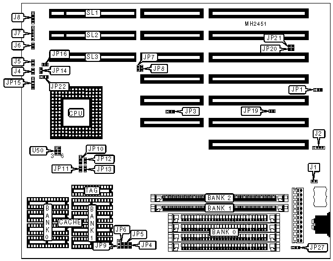
CONNECTIONS | |||
|
Purpose |
Location |
Purpose |
Location |
|
External battery |
J2 |
Speaker |
J8 |
|
Reset switch |
J4 |
Green PC connector |
JP19 |
|
Turbo LED |
J5 |
Green PC connector |
JP20 |
|
Turbo switch |
J6 |
Green PC connector |
JP21 |
|
Power LED & keylock |
J7 |
32-bit VESA local bus slots |
SL1 - SL3 |
|
USER CONFIGURABLE SETTINGS | |||
|
Function |
Jumper |
Position | |
|
» |
Battery type select internal |
J1 |
Closed |
|
Battery type select external |
J1 |
Open | |
|
» |
Power good signal detect from power supply |
JP1 |
pins 1 & 2 closed |
|
Power good signal detect from board |
JP1 |
pins 2 & 3 closed | |
|
» |
VESA card select normal |
JP3 |
pins 1 & 2 closed |
|
VESA card select Viper 9000 card only |
JP3 |
pins 2 & 3 closed | |
|
» |
Factory configured - do not alter |
JP7 |
Open |
|
» |
Factory configured - do not alter |
JP8 |
Open |
|
» |
DRAM bank select Bank 0 or Banks 1 & 2 used |
JP27 |
pins 1 & 2 closed |
|
DRAM bank select Banks 0, 1, & 2 used |
JP27 |
pins 2 & 3 closed | |
|
DRAM CONFIGURATION | |||
|
Size |
Bank 0 |
Bank 1 |
Bank 2 |
|
1MB |
(4) 256K x 9 |
NONE |
NONE |
|
2MB |
NONE |
(1) 256K x 36 |
(1) 256K x 36 |
|
2MB |
(4) 256K x 9 |
NONE |
(1) 256K x 36 |
|
4MB |
NONE |
(1) 512K x 36 |
(1) 512K x 36 |
|
4MB |
NONE |
(1) 1M x 36 |
NONE |
|
4MB |
(4) 1M x 9 |
NONE |
NONE |
|
6MB |
NONE |
(1) 1M x 36 |
(1) 512K x 36 |
|
6MB |
(4) 1M x 9 |
NONE |
(1) 512K x 36 |
|
8MB |
NONE |
(1) 1M x 36 |
(1) 1M x 36 |
|
8MB |
(4) 1M x 9 |
NONE |
(1) 1M x 36 |
|
12MB |
NONE |
(1) 2M x 36 |
(1) 1M x 36 |
|
12MB |
(4) 1M x 9 |
NONE |
(1) 2M x 36 |
|
16MB |
NONE |
(1) 2M x 36 |
(1) 2M x 36 |
|
16MB |
(4) 4M x 9 |
NONE |
NONE |
|
24MB |
NONE |
(1) 4M x 36 |
(1) 2M x 36 |
|
24MB |
(4) 4M x 9 |
NONE |
(1) 2M x 36 |
|
32MB |
NONE |
(1) 4M x 36 |
(1) 4M x 36 |
|
32MB |
(4) 4M x 9 |
NONE |
(1) 4M x 36 |
|
CACHE CONFIGURATION | |||
|
Size |
Bank 0 |
Bank 1 |
TAG |
|
32KB |
(4) 8K x 8 |
NONE |
(1) 8K x 8 |
|
64KB |
(4) 8K x 8 |
(4) 8K x 8 |
(1) 8K x 8 |
|
128KB |
(4) 32K x 8 |
NONE |
(1) 8K x 8 |
|
256KB |
(4) 32K x 8 |
(4) 32K x 8 |
(1) 32K x 8 |
|
Note: The actual location of the cache banks may vary. | |||
|
CACHE JUMPER CONFIGURATION | |||||
|
Size |
JP9 |
JP10 |
JP11 |
JP12 |
JP13 |
|
32KB |
2 & 3 |
Open |
Open |
Open |
Open |
|
64KB |
1 & 2 |
Open |
Open |
Open |
Closed |
|
128KB |
2 & 3 |
2 & 3 |
Open |
Closed |
Closed |
|
256KB |
1 & 2 |
1 & 2 |
Closed |
Closed |
Closed |
|
Note: Pins designated should be in the closed position. | |||||
|
CPU TYPE CONFIGURATION | |||
|
Type |
JP14 |
JP15 |
U50 |
|
80486SX |
Open |
2 & 3 |
3 & 6, 4 & 5 |
|
80486DX |
1 & 2 |
1 & 2, 3 & 4 |
3 & 6, 4 & 5 |
|
80486DX2 |
1 & 2 |
1 & 2, 3 & 4 |
3 & 6, 4 & 5 |
|
80486DX4 |
1 & 2 |
1 & 2, 3 & 4 |
uses voltage converter |
|
Note: Pins designated should be in the closed position. | |||
|
CPU SPEED CONFIGURATION | |||
|
Speed |
JP4 |
JP5 |
JP6 |
|
25MHz |
Closed |
Open |
Open |
|
33MHz |
Closed |
Closed |
Closed |
|
50iMHz |
Closed |
Open |
Open |
|
50MHz |
Open |
Open |
Closed |
|
66iMHz |
Closed |
Closed |
Closed |
|
100iMHz |
Closed |
Closed |
Closed |
|
CPU CLOCK SPEED CONFIGURATION | |
|
Speed |
JP22 |
|
1.5x |
pins 2 & 3 closed |
|
2x |
pins 1 & 2 closed |
|
3x |
Open |
|
BUS SPEED CONFIGURATION | |
|
CPU speed |
JP16 |
|
<= 33MHz |
Open |
|
> 33MHz |
Closed |