ICL
VALUEPLUS MD/P60 SERIES
|
Processor |
Pentium |
|
Processor Speed |
60MHz |
|
Chip Set |
Intel |
|
Max. Onboard DRAM |
96MB |
|
Cache |
256/512KB |
|
BIOS |
Acer |
|
Dimensions |
330mm x 218mm |
|
I/O Options |
PS/2 mouse port, parallel port, serial ports (2), 32-bit PCI slots (3), floppy drive interface, IDE interface |
|
NPU Options |
None |
|
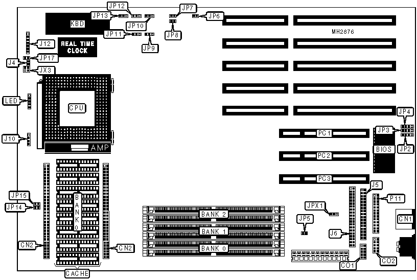
CONNECTIONS | |||
|
Purpose |
Location |
Purpose |
Location |
|
PS/2 mouse port |
CN1 |
Auxiliary keyboard connector |
J12 |
|
Serial port 1 |
CO1 |
+5v ground |
JP9 |
|
Serial port 2 |
CO2 |
IDE interface LED |
JX3 |
|
IDE interface LED |
J4 |
Power LED & keylock |
LED |
|
Floppy drive interface |
J5 |
Parallel port |
P11 |
|
IDE interface |
J6 |
32-bit PCI slots |
PC1 - PC3 |
|
Chassis fan power |
J10 | ||
|
USER CONFIGURABLE SETTINGS | |||
|
Function |
Jumper |
Position | |
|
» |
On board I/O enabled |
JP5 |
Closed |
|
On board I/O disabled |
JP5 |
Open | |
|
» |
Parallel port bidirectional |
JP6 |
Closed |
|
Parallel port unidirectional |
JP6 |
Open | |
|
» |
Password disabled |
JP11 |
pins 2 & 3 closed |
|
Password enabled |
JP11 |
pins 1 & 2 closed | |
|
» |
Cache type select standard cache |
JP13 |
pins 1 & 2 closed |
|
Cache type select burst cache |
JP13 |
pins 2 & 3 closed | |
|
» |
Keylock disabled |
JP17 |
Closed |
|
Keylock enabled |
JP17 |
Open | |
|
» |
Ground pin 28 hard disk drive |
JPX1 |
pins 2 & 3 closed |
|
HALE pin 28 |
JPX1 |
pins 1 & 2 closed | |
|
DRAM CONFIGURATION | |||
|
Size |
Bank 0 |
Bank 1 |
Bank 2 |
|
8MB |
(2) 1M x 36 |
NONE |
NONE |
|
16MB |
(2) 1M x 36 |
(2) 1M x 36 |
NONE |
|
24MB |
(2) 1M x 36 |
(2) 1M x 36 |
(2) 1M x 36 |
|
32MB |
(2) 4M x 36 |
NONE |
NONE |
|
40MB |
(2) 1M x 36 |
(2) 4M x 36 |
NONE |
|
40MB |
(2) 4M x 36 |
(2) 1M x 36 |
NONE |
|
48MB |
(2) 1M x 36 |
(2) 1M x 36 |
(2) 4M x 36 |
|
48MB |
(2) 1M x 36 |
(2) 4M x 36 |
(2) 1M x 36 |
|
48MB |
(2) 4M x 36 |
(2) 1M x 36 |
(2) 1M x 36 |
|
64MB |
(2) 4M x 36 |
(2) 4M x 36 |
NONE |
|
72MB |
(2) 1M x 36 |
(2) 4M x 36 |
(2) 4M x 36 |
|
72MB |
(2) 4M x 36 |
(2) 1M x 36 |
(2) 4M x 36 |
|
72MB |
(2) 4M x 36 |
(2) 4M x 36 |
(2) 1M x 36 |
|
96MB |
(2) 4M x 36 |
(2) 4M x 36 |
(2) 4M x 36 |
|
CACHE CONFIGURATION | ||
|
Size |
Bank 0 |
CN2 |
|
256KB |
(8) 32K x 8 |
NONE |
|
512KB |
(8) 32K x 8 |
Card installed |
|
Note: To use 512KB cache, a cache card must be installed at CN2. | ||
|
CACHE JUMPER CONFIGURATION | ||
|
Size |
JP10 |
JP12 |
|
None |
pins 1 & 2 closed |
pins 1 & 2 closed |
|
256KB |
pins 2 & 3 closed |
pins 1 & 2 closed |
|
512KB |
pins 2 & 3 closed |
pins 2 & 3 closed |
|
CACHE OE# SIGNAL CONFIGURATION | ||
|
Size |
JP14 |
JP15 |
|
256KB cache enabled |
Closed |
Closed |
|
256KB cache disabled |
Open |
Open |
|
L2 PARITY CHECK CONFIGURATION | ||
|
Setting |
JP7 |
JP8 |
|
Disabled |
Closed |
Closed |
|
Enabled |
Open |
Open |
|
PCI IRQ CONFIGURATION (INT B) | |
|
IRQ |
JP2 |
|
Disabled |
pins 2 & 3 closed |
|
IRQ14 |
pins 3 & 4 closed |
|
IRQ15 |
pins 1 & 2 closed |
|
PCI IRQ CONFIGURATION (INT C) | |
|
IRQ |
JP3 |
|
Disabled |
pins 2 & 3 closed |
|
IRQ11 |
pins 1 & 2 closed |
|
IRQ15 |
pins 3 & 4 closed |
|
PCI IRQ CONFIGURATION (INT D) | |
|
IRQ |
JP4 |
|
Disabled |
pins 2 & 3 closed |
|
IRQ10 |
pins 1 & 2 closed |
|
IRQ15 |
pins 3 & 4 closed |