QUATECH, INC.
DS-200/DS-300/DS-300S
|
Card Type |
Serial controller |
|
Chipset/Controller |
16450 |
|
I/O Options |
Serial ports (2) |
|
Maximum DRAM |
N/A |
|
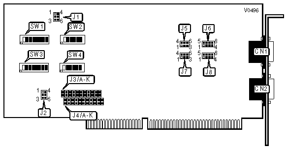
CONNECTIONS | |||
|
Purpose |
Location |
Purpose |
Location |
|
Serial port 1 |
CN1 |
Serial port 2 |
CN2 |
|
INPUT CLOCK CONFIGURATION | ||
|
MHz |
J1 | |
| » |
1.8432MHz |
Pins 1 & 2, 3 & 6, 4 & 5 closed |
|
3.6864MHz |
Pins 2 & 3, 4 & 5 closed | |
|
9.216MHz |
Pins 1 & 2, 5 & 6 closed | |
|
18.432MHz |
Pins 2 & 5 closed | |
|
PRIMARY PORT BASE MEMORY ADDRESS SELECT | |||
|
Address |
SW1 |
SW2 | |
| » |
03F8h |
Switches 1 & 2, 3 & 4, 5 & 6 on |
All Off |
|
02E0h |
Switches 1 & 2, 3 & 4, 5 & 6, 8 on |
Switches 4 & 5 on | |
|
02F8h |
Switches 1 & 2, 3 & 4, 5 & 6, 8 on |
All Off | |
|
03E8h |
Switches 1 & 2, 3 & 4, 5 & 6 on |
Switch 4 on | |
|
Note:All switches other than those designated as on should be placed in the Off position. | |||
|
ALTERNATE PORT BASE MEMORY ADDRESS SELECT | |||
|
Address |
SW3 |
SW4 | |
| » |
02F8h |
Switches 1 & 2, 3 & 4, 5 & 6, 8 on |
All Off |
|
02E0h |
Switches 1 & 2, 3 & 4, 5 & 6, 8 on |
Switches 4 & 5 on | |
|
03E8h |
Switches 1 & 2, 3 & 4, 5 & 6 on |
Switch 4 on | |
|
03F8h |
Switches 1 & 2, 3 & 4, 5 & 6 on |
All Off | |
|
Note:All switches other than those designated as on should be placed in the Off position. | |||
|
PRIMARY PORT INTERRUPT SELECT | |
|
IRQ |
J3 |
|
IRQ2 |
Jumper A closed |
|
IRQ3 |
Jumper B closed |
|
IRQ4 |
Jumper C closed |
|
IRQ5 |
Jumper D closed |
|
IRQ6 |
Jumper E closed |
|
IRQ7 |
Jumper F closed |
|
IRQ10 |
Jumper G closed |
|
IRQ11 |
Jumper H closed |
|
IRQ12 |
Jumper I closed |
|
IRQ14 |
Jumper J closed |
|
IRQ15 |
Jumper K closed |
|
Note: All jumpers other than those designated should be in the open position. | |
|
ALTERNATE PORT INTERRUPT SELECT | |
|
IRQ |
J4 |
|
IRQ2 |
Jumper A closed |
|
IRQ3 |
Jumper B closed |
|
IRQ4 |
Jumper C closed |
|
IRQ5 |
Jumper D closed |
|
IRQ6 |
Jumper E closed |
|
IRQ7 |
Jumper F closed |
|
IRQ10 |
Jumper G closed |
|
IRQ11 |
Jumper H closed |
|
IRQ12 |
Jumper I closed |
|
IRQ14 |
Jumper J closed |
|
IRQ15 |
Jumper K closed |
|
Note: All jumpers other than those designated should be in the open position. | |
|
PRIMARY PORT INTERRUPT SHARING | ||
|
Setting |
J2 | |
| » |
Dedicated interrupt level |
Pins 1 & 2 closed |
|
Interrupt sharing |
Pins 2 & 3 closed | |
|
ALTERNATE PORT INTERRUPT SHARING | ||
|
Setting |
J2 | |
| » |
Dedicated interrupt level |
Pins 4 & 5 closed |
|
Interrupt sharing |
Pins 5 & 6 closed | |
|
PRIMARY PORT AUXILIARY CHANNEL CONFIGURATION | |||
|
Transmission |
Reception |
Loopback |
J5 |
|
RTS |
CTS |
XCLK/RCLK |
Pins 1 & 2, 3 & 6, 4 & 5 closed |
|
XCLK |
RCLK |
RTS/CTS |
Pins 1 & 4, 2 & 3, 5 & 6 closed |
|
N/A |
N/A |
RTS/CTS/XCLK/RCLK/AUXOUT/AUXIN |
Pins 1 & 4, 2 & 5, 3 & 6 closed |
|
ALTERNATE PORT AUXILIARY CHANNEL CONFIGURATION | |||
|
Transmission |
Reception |
Loopback |
J7 |
|
RTS |
CTS |
XCLK/RCLK |
Pins 1 & 2, 3 & 6, 4 & 5 closed |
|
XCLK |
RCLK |
RTS/CTS |
Pins 1 & 4, 2 & 3, 5 & 6 closed |
|
N/A |
N/A |
RTS/CTS/XCLK/RCLK/AUXOUT/AUXIN |
Pins 1 & 4, 2 & 5, 3 & 6 closed |
|
PRIMARY PORT DRIVER CONFIGURATION | |
|
Driver |
J6 |
|
- DTR |
Pins 1 & 5 closed |
|
+ DTR |
Pins 2 & 6 closed |
|
- RTS |
Pins 3 & 7 closed |
|
+ RTS |
Pins 4 & 8 closed |
|
ALTERNATE PORT DRIVER CONFIGURATION | |
|
Driver |
J8 |
|
- DTR |
Pins 1 & 5 closed |
|
+ DTR |
Pins 2 & 6 closed |
|
- RTS |
Pins 3 & 7 closed |
|
+ RTS |
Pins 4 & 8 closed |