NATIONAL INSTRUMENTS
AT-MIO-16
|
Card Type |
Analog to digital timing converter |
|
Chipset Controller |
Unidentified |
|
I/O Options |
Analog input, analog output, digital input, digital output |
|
Maximum DRAM |
N/A |
|
CONNECTIONS | |||
|
Purpose |
Location |
Purpose |
Location |
|
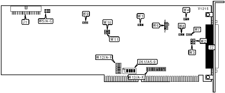
34-pin interface connector |
J1 |
100-pin I/O connector |
J2 |
|
BASE I/O ADDRESS SELECTION | ||||||
|
Address |
U61/A5 |
U61/A6 |
U61/A7 |
U61/A8 |
U61/A9 | |
| » |
220h |
Off |
On |
On |
On |
Off |
|
180h |
On |
On |
Off |
Off |
On | |
|
1A0h |
Off |
On |
Off |
Off |
On | |
|
1C0h |
On |
Off |
Off |
Off |
On | |
|
1E0h |
Off |
Off |
Off |
Off |
On | |
|
200h |
On |
On |
On |
On |
Off | |
|
360h |
Off |
Off |
On |
Off |
Off | |
|
380h |
On |
On |
Off |
Off |
Off | |
|
3A0h |
Off |
On |
Off |
Off |
Off | |
|
3C0h |
On |
Off |
Off |
Off |
Off | |
|
3E0h |
Off |
Off |
Off |
Off |
Off | |
|
Note: A total of 255 base address settings are available. The switches are a binary representation of the decimal memory addresses. Switch A9 is the Most Significant Bit and switch A5 is the Least Significant Bit. The switches have the following decimal values: switch A9=512, A8=256, A7=128, A6=64, A5=32. Turn On the switches and add the values of the switches that are On to obtain the correct memory address. (Off=1, On=0) | ||||||
|
DMA CHANNEL SELECTION (DMA 1) | |||||||
|
DMA |
W12/A |
W12/B |
W12/C |
W12/D |
W12/E |
W12/F | |
| » |
6 |
Open |
Open |
Pins 1 & 2 |
Pins 1 & 2 |
Open |
Open |
|
5 |
Open |
Open |
Open |
Open |
Pins 1 & 2 |
Pins 1 & 2 | |
|
7 |
Pins 1 & 2 |
Pins 1 & 2 |
Open |
Open |
Open |
Open | |
|
Disabled |
Open |
Open |
Open |
Open |
Open |
Open | |
|
Note: Pins designated are in the closed position. | |||||||
|
DMA CHANNEL SELECTION (DMA 2) | |||||||
|
DMA |
W12/A |
W12/B |
W12/C |
W12/D |
W12/E |
W12/F | |
| » |
7 |
Pins 2 & 3 |
Pins 2 & 3 |
Open |
Open |
Open |
Open |
|
5 |
Open |
Open |
Open |
Open |
Pins 2 & 3 |
Pins 2 & 3 | |
|
6 |
Open |
Open |
Pins 2 & 3 |
Pins 2 & 3 |
Open |
Open | |
|
Disabled |
Open |
Open |
Open |
Open |
Open |
Open | |
|
Note: Pins designated are in the closed position. | |||||||
|
INTERRUPT SELECTION (MIO-16 CIRCUITRY) | |||||||
|
IRQ |
W13/A |
W13/B |
W13/C |
W13/D |
W13/E |
W13/F | |
| » |
10 |
Open |
Open |
Open |
Open |
Open |
Open |
|
2/9 |
Open |
Open |
Open |
Open |
Open |
1 & 2 | |
|
3 |
1 & 2 |
Open |
Open |
Open |
Open |
Open | |
|
4 |
Open |
1 & 2 |
Open |
Open |
Open |
Open | |
|
5 |
Open |
Open |
1 & 2 |
Open |
Open |
Open | |
|
6 |
Open |
Open |
Open |
1 & 2 |
Open |
Open | |
|
7 |
Open |
Open |
Open |
Open |
1 & 2 |
Open | |
|
11 |
Open |
Open |
Open |
Open |
Open |
Open | |
|
12 |
Open |
Open |
Open |
Open |
Open |
Open | |
|
14 |
Open |
Open |
Open |
Open |
Open |
Open | |
|
15 |
Open |
Open |
Open |
Open |
Open |
Open | |
|
Disabled |
Open |
Open |
Open |
Open |
Open |
Open | |
|
Note: Pins designated are in the closed position. | |||||||
|
INTERRUPT SELECTION (MIO-16 CIRCUITRY CON’T) | ||||||
|
IRQ |
W13/G |
W13/H |
W13/I |
W13/J |
W13/K | |
| » |
10 |
Closed |
Open |
Open |
Open |
Open |
|
2/9 |
Open |
Open |
Open |
Open |
Open | |
|
3 |
Open |
Open |
Open |
Open |
Open | |
|
4 |
Open |
Open |
Open |
Open |
Open | |
|
5 |
Open |
Open |
Open |
Open |
Open | |
|
6 |
Open |
Open |
Open |
Open |
Open | |
|
7 |
Open |
Open |
Open |
Open |
Open | |
|
11 |
Open |
Closed |
Open |
Open |
Open | |
|
12 |
Open |
Open |
Closed |
Open |
Open | |
|
14 |
Open |
Open |
Open |
Closed |
Open | |
|
15 |
Open |
Open |
Open |
Open |
Closed | |
|
Disabled |
Open |
Open |
Open |
Open |
Open | |
|
Note: Pins designated are in the closed position. | ||||||
|
ANALOG INPUT CONFIGURATION | |||
|
Type |
W6 |
W9 | |
| » |
DIFF |
Pins 1 & 3, 2 & 4, 5 & 6 closed |
Pins 1 & 2 closed |
|
RSE |
Pins 1 & 2, 3 & 4, 7 & 8 closed |
Pins 2 & 3 closed | |
|
NRSE |
Pins 1 & 2, 3 & 5, 7 & 8 closed |
Pins 2 & 3 closed | |
|
ANALOG INPUT POLARITY & RANGE CONFIGURATION | ||||
|
Range |
Polarity |
W1 |
W4 | |
| » |
-10 to +10V |
Bipolar input |
Pins 1 & 2 closed |
Pins 2 & 3 closed |
|
0 to +10V |
Unipolar input |
Pins 2 & 3 closed |
Pins 1 & 2 closed | |
|
-5 to +5V |
Bipolar input |
Pins 2 & 3 closed |
Pins 2 & 3 closed | |
|
ANALOG OUTPUT CONFIGURATION | |||
|
Type |
W2 (Channel 1) |
W3 (Channel 0) | |
| » |
Internal |
Pins 2 & 3 closed |
Pins 2 & 3 closed |
|
External |
Pins 1 & 2 closed |
Pins 1 & 2 closed | |
|
ANALOG OUTPUT POLARITY CONFIGURATION | |||
|
Type |
W7 (Channel 1) |
W8 (Channel 0) | |
| » |
Bipolar |
Pins 1 & 2 closed |
Pins 1 & 2 closed |
|
Unipolar |
Pins 2 & 3 closed |
Pins 2 & 3 closed | |
|
Note: Use this table in conjunction with the table below to set jumpers for Bipolar & Unipolar mode selection. | |||
|
BIPOLAR & UNIPOLAR OUTPUT MODE CONFIGURATION | |||
|
Mode |
W10 (Channel 0) |
W11 (Channel 1) | |
| » |
Two’s Complement |
Pins 1 & 2 closed |
Pins 1 & 2 closed |
|
Straight Binary (Unipolar) |
Pins 2 & 3 closed |
Pins 2 & 3 closed | |
|
Note: Bipolar can use both modes, while Unipolar uses the straight binary mode only. | |||
|
RTSI BUS CLOCK CONFIGURATION | ||||
|
Setting |
W5/A |
W5/B |
W5/C | |
| » |
Use local oscillator board |
Open |
Closed |
Closed |
|
Receive the RTSI bus signal |
Closed |
Open |
Closed | |
|
Drive RTSI bus & board/OSC |
Closed |
Closed |
Open | |