CONNECT TECH, INC.
DFLEX-2
|
Card Type |
Serial card |
|
Chipset Controller |
UART 16450 or 16550 |
|
I/O Options |
Serial port (2) |
|
Maximum DRAM |
N/A |
|
CONNECTIONS | |||
|
Purpose |
Location |
Purpose |
Location |
|
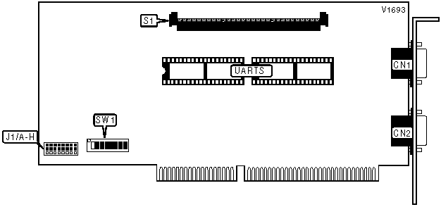
9-pin serial port connector |
CN1 |
*SLIM connector (Port 1 & 2) |
S1 |
|
9-pin serial port connector |
CN2 | ||
|
*Note: Serial Line Interface Module (SLIM) connectors. | |||
|
SERIAL PORT 1 | |
|
Setting |
SW1/1 |
|
COM1 (3F8h) |
On |
|
User select |
Off |
|
Note: When SW1/1 is set in the off position refer to Serial & Status Port Address table. | |
|
SERIAL PORT 2 | |
|
Setting |
SW1/2 |
|
COM2 (2F8h) |
On |
|
User select |
Off |
|
Note: When SW1/2 is set in the off position refer to Serial & Status Port Address table. | |
|
SERIAL & STATUS PORT ADDRESS | |||||
|
Port 1 |
Port 2 |
Status port |
SW1/3 |
SW1/4 |
SW1/5 |
|
200h |
208h |
240h |
On |
On |
On |
|
240h |
248h |
280h |
On |
On |
Off |
|
280h |
288h |
2C0h |
On |
Off |
On |
|
2C0h |
2C8h |
300h |
On |
Off |
Off |
|
300h |
308h |
340h |
Off |
On |
On |
|
2B0h |
2B8h |
288h |
Off |
On |
Off |
|
290h |
298h |
2D0h |
Off |
Off |
On |
|
190h |
198h |
1D0h |
Off |
Off |
Off |
|
STATUS PORT | |
|
Setting |
SW1/7 |
|
Enabled |
On |
|
Disabled |
Off |
|
INTERRUPT CHANNEL A | ||||
|
IRQ |
J1/A |
J1/B |
J1/C |
J1/D |
|
3 |
Pins 1 & 2 closed |
Open |
Open |
Open |
|
4 |
Open |
Pins 1 & 2 closed |
Open |
Open |
|
5 |
Open |
Open |
Pins 1 & 2 closed |
Open |
|
7 |
Open |
Open |
Open |
Pins 1 & 2 closed |
|
10 |
Open |
Open |
Open |
Open |
|
11 |
Open |
Open |
Open |
Open |
|
12 |
Open |
Open |
Open |
Open |
|
15 |
Open |
Open |
Open |
Open |
|
INTERRUPT CHANNEL A (CON’T) | |||||
|
iRQ |
J1/E |
J1/F |
J1/G |
J1/H |
SW1/8 |
|
3 |
Open |
Open |
Open |
Open |
On |
|
4 |
Open |
Open |
Open |
Open |
On |
|
5 |
Open |
Open |
Open |
Open |
On |
|
7 |
Open |
Open |
Open |
Open |
On |
|
10 |
Pins 1 & 2 closed |
Open |
Open |
Open |
On |
|
11 |
Open |
Pins 1 & 2 closed |
Open |
Open |
On |
|
12 |
Open |
Open |
Pins 1 & 2 closed |
Open |
On |
|
15 |
Open |
Open |
Open |
Pins 1 & 2 closed |
On |
|
Note: When port 1 is configured as COM1 & port 2 is configured as COM2, SW1/8 should be in the off position. IRQ4 (COM1) should have channel A settings & IRQ3 (COM2) should have channel B settings. If only one of the first two ports is configured as COM1 or COM2, the other jumper can be moved or removed according to the requirements of the software being used. | |||||
|
INTERRUPT CHANNEL B | ||||
|
IRQ |
J1/A |
J1/B |
J1/C |
J1/D |
|
3 |
Pins 2 & 3 closed |
Open |
Open |
Open |
|
4 |
Open |
Pins 2 & 3 closed |
Open |
Open |
|
5 |
Open |
Open |
Pins 2 & 3 closed |
Open |
|
7 |
Open |
Open |
Open |
Pins 2 & 3 closed |
|
10 |
Open |
Open |
Open |
Open |
|
11 |
Open |
Open |
Open |
Open |
|
12 |
Open |
Open |
Open |
Open |
|
15 |
Open |
Open |
Open |
Open |
|
INTERRUPT CHANNEL B (CON’T) | |||||
|
IRQ |
J1/E |
J1/F |
J1/G |
J1/H |
SW1/8 |
|
3 |
Open |
Open |
Open |
Open |
Off |
|
4 |
Open |
Open |
Open |
Open |
Off |
|
5 |
Open |
Open |
Open |
Open |
Off |
|
7 |
Open |
Open |
Open |
Open |
Off |
|
10 |
Pins 2 & 3 closed |
Open |
Open |
Open |
Off |
|
11 |
Open |
Pins 2 & 3 closed |
Open |
Open |
Off |
|
12 |
Open |
Open |
Pins 2 & 3 closed |
Open |
Off |
|
15 |
Open |
Open |
Open |
Pins 2 & 3 closed |
Off |
|
Note: When port 1 is configured as COM1 & port 2 is configured as COM2, SW1/8 should be in the off position. IRQ4 (COM1) should have channel A settings & IRQ3 (COM2) should have channel B settings. If only one of the first two ports is configured as COM1 or COM2, the other jumper can be moved or removed according to the requirements of the software being used. | |||||
|
FACTORY CONFIGURED - DO NOT ALTER | |
|
Switch |
Position |
|
SW1/6 |
Off |