UNIDENTIFIED
MV-500
|
| |
|
Data bus: |
16-bit ISA |
|
Size: |
Half-length, full-height card |
|
Hard drive supported: |
Two IDE (AT) interface drives |
|
Floppy drives supported: |
Two 360KB, 720KB, 1.2MB, or 1.44MB drives |
|
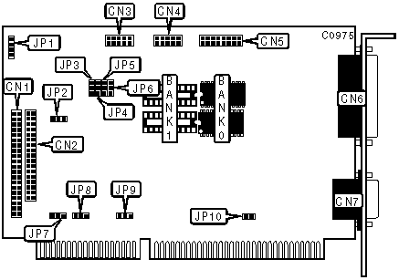
CONNECTIONS | |
|
Function |
Location |
|
40-pin primary IDE(AT) connector |
CN1 |
|
34-pin cable connector - floppy drive |
CN2 |
|
10-pin serial port 1 - internal |
CN3 |
|
10-pin serial port 2 - internal |
CN4 |
|
16-pin game port |
CN5 |
|
25-pin parallel port - external |
CN6 |
|
15-pin analog video port - external |
CN7 |
|
4-pin connector - drive active LED |
JP1 |
|
USER CONFIGURABLE SETTINGS | |||
|
Function |
Location |
Setting | |
| » |
Serial port 2 enabled |
JP3 |
Pins 1 & 2 closed |
|
Serial port 2 disabled |
JP3 |
Pins 2 & 3 closed | |
| » |
Serial port 1 enabled |
JP4 |
Pins 1 & 2 closed |
|
Serial port 1 disabled |
JP4 |
Pins 2 & 3 closed | |
| » |
Game port enabled |
JP5 |
Pins 1 & 2 closed |
|
Game port disabled |
JP5 |
Pins 2 & 3 closed | |
| » |
Parallel port LPT1(378h) select |
JP6 |
Pins 1 & 2 closed |
|
Parallel port LPT2(278h) select |
JP6 |
Pins 2 & 3 closed | |
| » |
Floppy drive interface enabled |
JP7 |
Pins 1 & 2 closed |
|
Floppy drive interface disabled |
JP7 |
Pins 2 & 3 closed | |
| » |
IDE(AT) interface enabled |
JP8 |
Pins 1 & 2 closed |
|
IDE(AT) interface disabled |
JP8 |
Pins 2 & 3 closed | |
| » |
Controller is only one present in system |
JP9 |
Pins 1 & 2 closed |
|
Other controllers are present in system |
JP9 |
Pins 2 & 3 closed | |
| » |
Wait state 0 enabled |
JP10 |
Closed |
|
Wait state 0 disabled |
JP10 |
Open | |
|
Note: Jumper JP2 is optional IOCHRDY connector for IDE. Settings are unidentified. | |||
|
DRAM CONFIGURATION | ||
|
Size |
Bank 0 |
Bank 1 |
|
256KB |
(2) 256K x 4 |
NONE |
|
512KB |
(2) 256K x 4 |
(2) 256K x 4 |
|
Note: Exact orientation of chips in Bank 0 & Bank 1 is unidentified. | ||